Control an LED with Raspberry Pi GPIO using C#
Published: January 14, 2026
Controlling hardware with software is one of the most rewarding aspects of working with a Raspberry Pi. In this tutorial, you’ll learn how to wire up an LED to your Raspberry Pi and control it using C# and the GPIO (General Purpose Input/Output) controller. This is a foundational skill for building more complex IoT projects.
By the end of this guide, you’ll have a blinking LED controlled by C# code running on your Raspberry Pi. This tutorial assumes you have .NET already installed on your Raspberry Pi — if you haven’t done that yet, check out my guide on installing .NET on Raspberry Pi.
Understanding the Circuit
Before we start wiring, let’s understand what we’re building. An LED (Light Emitting Diode) needs a current-limiting resistor to prevent it from burning out. The Raspberry Pi’s GPIO pins output 3.3V, and without a resistor, too much current would flow through the LED, potentially damaging both the LED and the GPIO pin.
Selecting the Correct Resistor
Choosing the right resistor is critical for a safe and functional circuit. Here’s how to calculate it:
Understanding the Requirements:
- Raspberry Pi GPIO Output: 3.3V (when set to HIGH)
- Typical LED Forward Voltage (V_LED): ~2.0V (red LED), varies by color:
- Red: 1.8-2.2V
- Green/Yellow: 2.0-2.2V
- Blue/White: 3.0-3.4V
- Desired LED Current (I_LED): 10-20mA (typical for standard 5mm LEDs)
- Maximum Safe GPIO Current: 16mA per pin
Using Ohm’s Law to Calculate:
Ohm’s Law states: V = I × R, which we rearrange to: R = V / I
The voltage across the resistor is: V_resistor = V_supply - V_LED
For a red LED with 3.3V supply and 2.0V forward voltage:
R = (V_supply - V_LED) / I_desired
R = (3.3V - 2.0V) / 0.020A
R = 1.3V / 0.020A
R = 65Ω minimum
Why We Use 330Ω Instead of 65Ω:
While 65Ω is the calculated minimum, we use 330Ω (or values in the 220-470Ω range) for several important reasons:
- Safety Margin: It keeps current well below the GPIO’s 16mA maximum limit
- LED Longevity: Lower current (around 4-10mA) extends LED lifespan
- Brightness: Even at lower current, the LED is still plenty bright for most applications
- Standard Value: 330Ω is a common resistor value, readily available
Actual Current with 330Ω:
I = (V_supply - V_LED) / R
I = (3.3V - 2.0V) / 330Ω
I = 1.3V / 330Ω
I = 0.0039A = 3.9mA
This 3.9mA is well within safe limits and still produces visible light.
Reading Resistor Color Codes:
A 330Ω resistor has these color bands:
- 1st band (Orange): 3
- 2nd band (Orange): 3 → Combined: 33
- 3rd band (Brown): ×10 → 33 × 10 = 330Ω
- 4th band (Gold): ±5% tolerance
Acceptable Resistor Values:
- 220Ω (Red-Red-Brown): Higher current (~5.9mA), brighter LED
- 330Ω (Orange-Orange-Brown): Recommended balance (~3.9mA)
- 470Ω (Yellow-Violet-Brown): Lower current (~2.8mA), dimmer but very safe
All of these values will work fine. The LED will just be slightly brighter or dimmer depending on the resistor value you choose.
Circuit Diagram
Here’s the complete circuit diagram for our LED project:
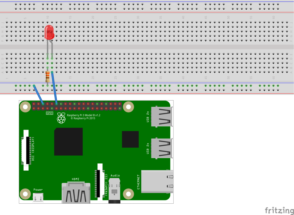
The circuit shows the LED connected through a 330Ω resistor from GPIO 18 (physical pin 12) to ground (physical pin 6). This is a simple series circuit — when GPIO 18 is set HIGH (3.3V), current flows through the resistor, lights the LED, and returns to ground.
Components Needed
- Raspberry Pi (any model with GPIO pins — Pi 3, 4, or 5)
- Breadboard (any size, even a mini breadboard works)
- LED (any color, 5mm or 3mm standard LED)
- 330Ω Resistor (orange-orange-brown color bands, or anything 220-470Ω)
- Jumper wires (2 male-to-female wires for connecting Pi to breadboard)
Wiring the Circuit
Follow these steps carefully to wire up your LED circuit:
1. Identify the LED polarity:
- The LED has two legs of different lengths
- The longer leg is the anode (+) and connects to the positive voltage through the resistor
- The shorter leg is the cathode (-) and connects to ground
- If the legs have been trimmed, look for a flat edge on the LED body — that side is the cathode
2. Insert the components into the breadboard:
- Insert the LED into the breadboard, with the anode and cathode in different rows
- Insert one leg of the 330Ω resistor into the same row as the LED anode
- The other leg of the resistor goes into a separate empty row
3. Connect GPIO 18 to the resistor:
- Use a jumper wire (preferably red for visual clarity) to connect GPIO 18 (physical pin 12) from the Raspberry Pi to the resistor leg that’s NOT connected to the LED
- On Raspberry Pi models 3, 4, and 5, pin 12 is located on the left side, sixth pin down when the Pi is oriented with the GPIO pins at the top left
4. Connect ground to the LED cathode:
- Use a jumper wire (preferably black) to connect Ground (physical pin 6) from the Raspberry Pi to the same breadboard row as the LED cathode
- Pin 6 is on the right side, third pin down
5. Double-check your connections:
- Ensure the resistor is in series with the LED (current flows through resistor first, then LED, then to ground)
- Verify GPIO 18 connects to the resistor side
- Verify ground connects to the LED cathode (shorter leg or flat edge side)
GPIO Pin Reference
The Raspberry Pi has a 40-pin GPIO header. For this project, we’re using:
- Physical Pin 12 = GPIO 18 (BCM numbering) — Our control pin
- Physical Pin 6 = Ground — Our common return path
Note that there are two numbering schemes: physical pin numbers (1-40 based on position) and BCM GPIO numbers (based on the Broadcom chip layout). The .NET GPIO library uses BCM numbering, which is why we reference GPIO 17 in code even though it’s physical pin 12.
The C# Code
Now for the fun part — writing code to control the LED! We’ll use the System.Device.Gpio NuGet package, which provides cross-platform GPIO access.
Create a new console application:
dotnet new console -n LedBlink
cd LedBlink
Add the GPIO library:
dotnet add package System.Device.Gpio
Replace the contents of Program.cs with this code:
using System;
using System.Device.Gpio;
using System.Threading;

class Program
{
    static void Main(string[] args)
    {
        // Define which GPIO pin we're using (BCM numbering)
        const int ledPin = 18;

        // Define how many times to blink
        const int blinkCount = 10;

        Console.WriteLine("Starting LED blink demo...");
        Console.WriteLine($"Using GPIO {ledPin} (Physical Pin 12)");
        Console.WriteLine($"Will blink {blinkCount} times");

        // Create a GPIO controller
        using (var controller = new GpioController())
        {
            // Set up the pin as an output
            controller.OpenPin(ledPin, PinMode.Output);

            Console.WriteLine("LED initialized. Starting blink sequence...\n");

            // Blink the LED multiple times
            for (int i = 0; i < blinkCount; i++)
            {
                // Turn LED ON
                controller.Write(ledPin, PinValue.High);
                Console.WriteLine($"Blink {i + 1}/{blinkCount}: LED ON");
                Thread.Sleep(500); // Wait 500ms

                // Turn LED OFF
                controller.Write(ledPin, PinValue.Low);
                Console.WriteLine($"Blink {i + 1}/{blinkCount}: LED OFF");
                Thread.Sleep(500); // Wait 500ms
            }

            Console.WriteLine("\nBlink sequence complete!");

            // Clean up - ensure LED is off
            controller.Write(ledPin, PinValue.Low);
            controller.ClosePin(ledPin);
        }

        Console.WriteLine("GPIO resources released. Program complete.");
    }
}
Understanding the Code
Let’s break down what this code does:
GPIO Controller Initialization:
using (var controller = new GpioController())
This creates a GPIO controller instance that manages access to the Pi’s GPIO pins. The using statement ensures proper cleanup when we’re done.
Opening the Pin:
controller.OpenPin(ledPin, PinMode.Output);
This configures GPIO 18 as an output pin, meaning we can write values to it to control voltage levels.
Writing Pin Values:
controller.Write(ledPin, PinValue.High);  // LED ON (3.3V)
controller.Write(ledPin, PinValue.Low);   // LED OFF (0V)
PinValue.High sets the pin to 3.3V, which turns the LED on. PinValue.Low sets it to 0V (ground), turning the LED off.
Timing:
Thread.Sleep(500);
This pauses execution for 500 milliseconds (half a second), creating the blink effect. You can adjust this value to make the blinking faster or slower.
Cleanup:
controller.ClosePin(ledPin);
This releases the GPIO pin when we’re done, making it available for other programs.
Running the Code
To run your LED blink program:
dotnet run
You should see console output indicating the LED status, and your physical LED should blink on and off 10 times. Each blink lasts one second total (500ms on, 500ms off).
If the LED doesn’t light up, check these common issues:
- Verify the LED polarity — flip it around if it’s backwards
- Confirm the resistor is properly connected in series
- Check that your jumper wires are firmly connected to the correct GPIO pins
- Make sure you’re running the program with appropriate permissions
Extending the Project
Now that you have a basic LED control working, here are some ideas to expand your project:
Multiple LEDs: Connect additional LEDs to different GPIO pins and create patterns or sequences.
Button Input: Add a button connected to another GPIO pin to control the LED interactively.
PWM for Brightness: Use Pulse Width Modulation (PWM) to control LED brightness instead of just on/off.
Traffic Light Simulation: Use three LEDs (red, yellow, green) to simulate a traffic light sequence.
GPIO Safety Notes
When working with GPIO pins, keep these safety guidelines in mind:
- Never connect 5V to a GPIO pin — The Pi uses 3.3V logic and 5V can damage the pins
- Always use current-limiting resistors with LEDs — Direct connection can damage the GPIO pin
- Don’t exceed 16mA per pin — Each GPIO pin has a maximum current rating
- Don’t exceed 50mA total — All GPIO pins combined shouldn’t draw more than 50mA
Wrapping Up
You’ve now successfully wired up and controlled an LED using C# on a Raspberry Pi! This foundational skill opens the door to countless IoT projects. The System.Device.Gpio library provides a clean, cross-platform API for hardware control, and the same patterns you learned here apply to more complex components like motors, sensors, displays, and more.
The combination of Raspberry Pi’s accessible hardware and .NET’s powerful programming environment makes it easy to bring your hardware projects to life. Whether you’re building a home automation system, a robot, or a custom IoT device, you now have the fundamental skills to get started.
For more information on GPIO programming with .NET, check out the official documentation: .NET IoT Libraries
Happy making!